

The trouble with any 'smart' device such as a Nest thermostat or many other smart devices is that they require an internet connection and a company to be in business running a server that they connect to. As we have seen with Logitech a company can change its focus at anytime.
If the product you just bought requires a cloud service to be available to function, you don't own it.
2019 is the year I am taking back control of my smart devices by bringing as much 'smarts' back inside my LAN as possible. To do this I've recently been experimenting with Home Assistant which I have running in a docker container on my media server.
Edit on: Dec 1st 2019
WLED was just added to Home Assistant 0.120 and is in my opinion a much easier to use solution than this one. I've written about it in this post so go ahead and check that out! I also covered WLED for my new podcast, Self Hosted during a live hack session a recording of which will be available on Youtube under the JB extras feed. Happy hacking! </edit>
This article will detail how to build a fully open source, 3D printable smart LED strip for $16.38. Please note that the links below are Amazon affiliate links.
Full credit for many of the resources here must go to Bruh automation.
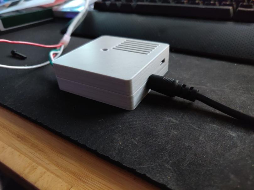
Here is a link to the case I designed on Thingiverse. It's not perfect, some of the tolerances are a little tight depending on your particular batch but it works well for me! I have the f3d file somewhere so if that's of interest find me on Twitter @ironicbadger.
Components
Here are the required components:
| Item | Price | Purpose |
|---|---|---|
| NodeMCU | $6.50 | Sends and receives commands to and from components |
| Voltage regulator | $1.33 | Converts 12v to 5v required by NodeMCU |
| Logic converter | $1.60 | Converts 3.3v signal to 5v required by LEDs |
| 12v DC PSU | $6.95 | Powaaaaah! |
| Total | $16.38 |
Now obviously, this does not include the price of the LED strip itself, there are many options available using the ubiquitous WS2811 controller. These typically range from $15-30 depending on LED density, waterproofing rating, etc. That said, I bought both a $15 strip and a $30 strip and found the $15 strip to be a bit dim and rubbish, go for the better one if you can.
We make use of the FastLED Arduino library. So whilst a WD2811 controller is not a requirement a FastLED library compatible one is. There's a section in the code we upload later where you can swap the controller out.
| Item | Price | Purpose |
|---|---|---|
| Better LED strip | $26.88 | 12v 60 LEDs/m IP65 Silicone Coating |
| Worse LED strip | $15.88 | 12 30 LEDs/m not waterproof |
So for $16.38 + $26.88 = $43.26 you have a 5 meter, smart, controllable LED strip with full RGB colors, dimming and it doesn't require a subscription or cloud service to operate.
3D printing a case
It's fair to say that my experience and skills with 3D modelling are next to zero. I've been using this project as a good excuse to learn Fusion 360. I recently purchased a Prusa i3 mk3 and wanted to put it use!
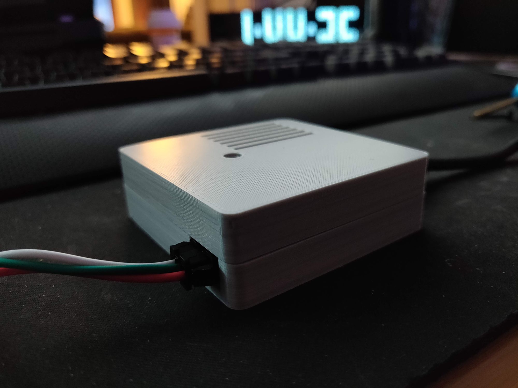
I'm working on making the case even smaller and on how to model snap catches to click the case together instead of using a bolt. It's a tight fit wiring everything up but it works great and temperatures of each component after 24 hours of running all the LEDs at full brightness never exceed 36c.
I'll upload the STL files to Thingiverse shortly. For those of you who don't have a 3D printer or are worried about soldering something so small, I'll happily print and ship a case anywhere in the USA for $5 plus shipping. A pre assembled project will be shipped out for $45 plus shipping (add your own PSU and LEDs). Contact me on Twitter @IronicBadger for more info or find me in the Linuxserver.io Discord.
Home Assistant Intro
I've only recently started dabbling in Home Assistant (HASS) but it is absolutely fantastic. HASS says this about itself "Open source home automation that puts local control and privacy first. Powered by a worldwide community of tinkerers and DIY enthusiasts. Perfect to run on a Raspberry Pi or a local server."
I already run an always on Linux media server and HASS is available as a docker container. Naturally, given my side project Linuxserver.io is heavily involved in the containerization scene it was a good fit.
All the files I use to configure Home Assistant can be found in this github repo. We'll take a look at how to actually configure Home Assistant towards the end of this article.
How does this work? MQTT. That's how.
MQTT is a very interesting area to understand as it allows us to react to events and do all sorts of cool stuff. Want to change your LEDs to a certain colour based on the status of your 3D printer? Or a timer? Or whether your mailbox has been opened? Or based on who's home?
This whole project makes use of MQTT. The MQTT protocol works on the concept of messages and topics. In our case, HASS is acting as the MQTT server.
When we click the button in HASS to 'turn on' the LED strip what actually happens is this. HASS sends a message to the specified MQTT topic. Your NodeMCU 'subscribes' to this topic and notices that an on_cmd message has been posted. The firmware we uploaded governs how the NodeMCU reacts to this. There are a number of messages supported including on_cmd, off_cmd, various RGB values or effectString.
This is super cool because this system allows the NodeMCU to provide feedback via a state topic. This means that HASS is actually aware of the current state of the LEDs. Think about that for a second. Traditional old automations (like Infrared based ones) are dumb. They just fire off commands and hope for the best. With MQTT that problem is solved!
Take the 3D printer example. Our LEDs might subscribe to a printer_status topic and our printer will publish to it. A 3D print might have 3 states inprogress, failed or completed. We want our LEDs to change colour to react to each of those events. When a print is inprogress the printer sends a message to the printer_status topic. Our LEDs are subscribed to this topic and see the inprogress message arrive and react accordingly. They could, but don't in this case, send a message back to the topic confirming receipt of that message and the printer could react to that and so on. Once our print has either entered a failed or completed state another message is published to the printer_status topic. The LEDs (which are subscribed to that topic) receive the message and act as programmed.
Your imagination really is the limit here.
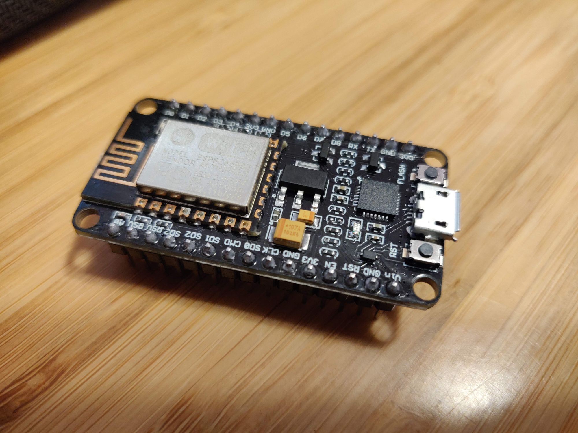
The Electronics
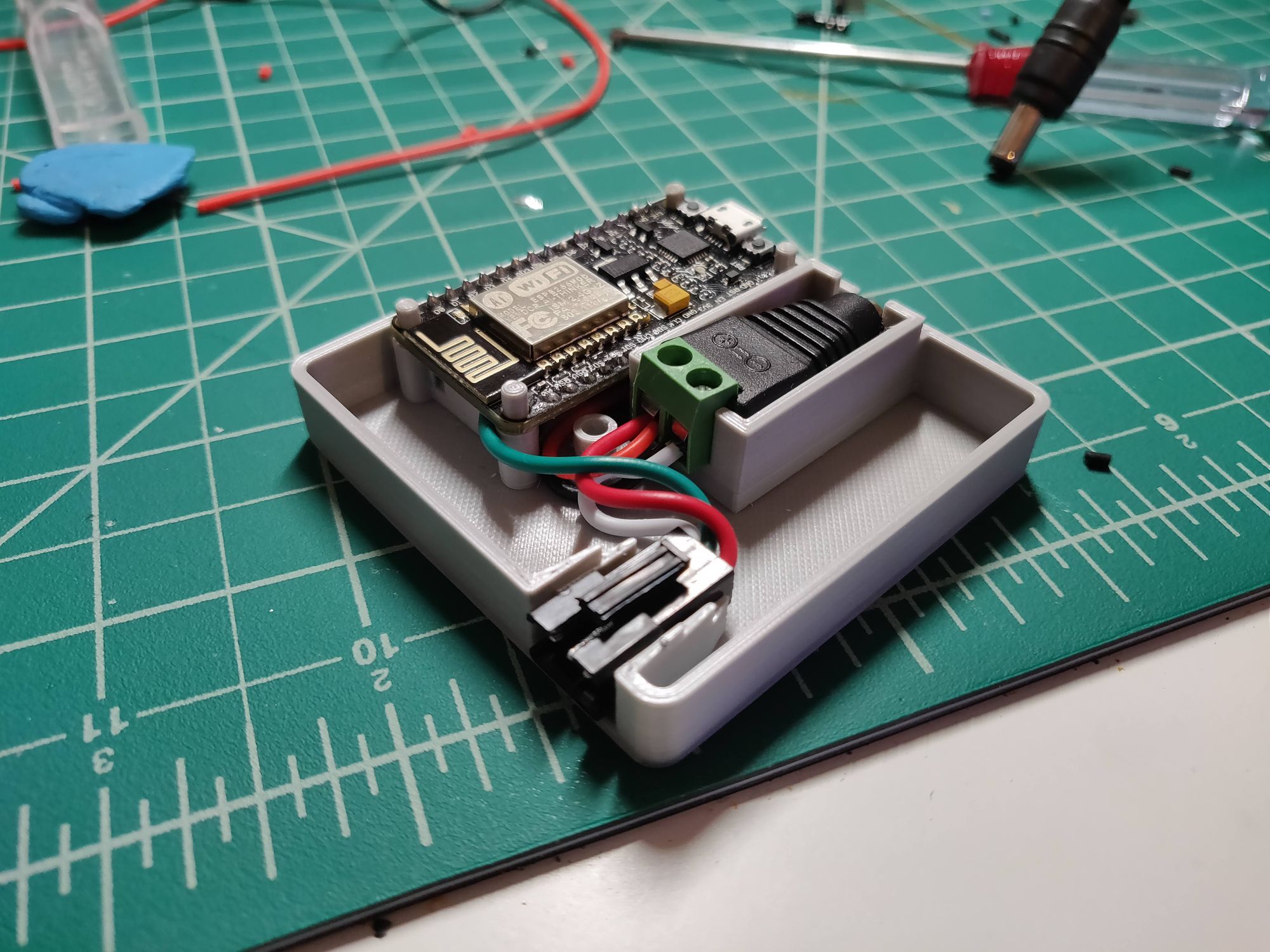
At the heart of this project is the NodeMCU which is based around the ESP8266 chip. It's inexpensive at $6.50, has wifi built-in and can be flashed using the ArduinoIDE via a built-in microUSB port.
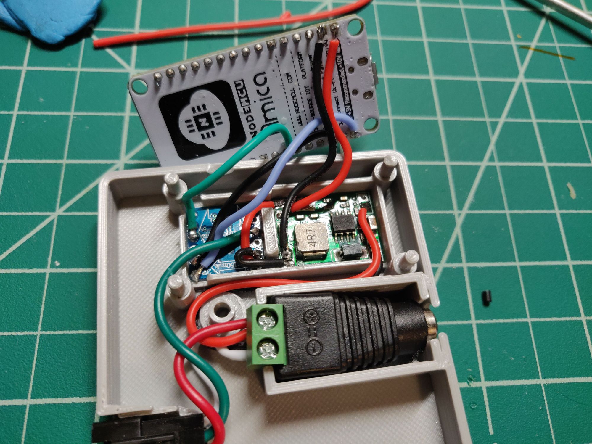
Wiring things up
Here's a diagram on how to connect everything up. The process of tuning the voltage regulator is a little fiddly and will require you to measure the output voltage with a multi-meter.
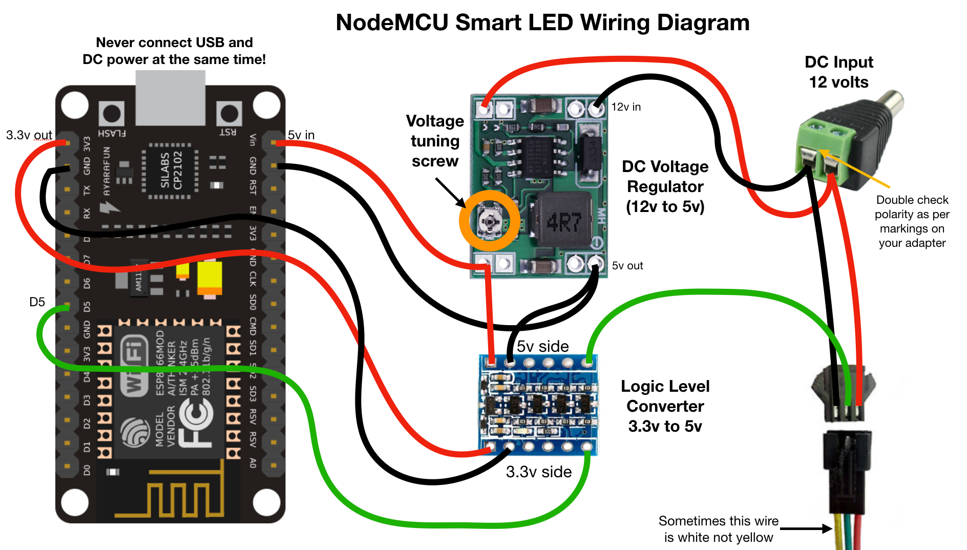
A few important notes here...
Voltages
We are working with 3 different voltages here. 12v, 5v and 3.3v.
Always triple check your voltages using a Multimeter.
We are using a 12v power supply as the LEDs require a 12v input. There's no sense in having a separate power supply for the electronics and the LEDs in my opinion so let's regulate the 12v input to the 5v our logic level converter and NodeMCU require. We do this using a voltage regulator.
The one I have selected is rated at up to 3 amps and supports a wide range of voltages which are adjustable using the voltage tuning screw (circled in orange). The NodeMCU and logic level converter is not going to use anywhere near 3 amps (I have noted a draw of 0.3a in my testing).
Tuning the regulator is actually quite simple but takes a bit of patience and practice. Connect the input +/- side of the regulator to the 12v inputs from the power supply triple check your polarity before plugging things in!! Next, grab a multimeter and connect it to the +/- output pins of the regulator. You'll see a random voltage at this point. We now need to tune it using the screw on the board. Slowly and carefully turn the screw left and right and watch the multimeter change accordingly. We are looking for a voltage as close to 5v as possible. In my testing anywhere between 5v and 5.5v was acceptable, closer to 5v is better.
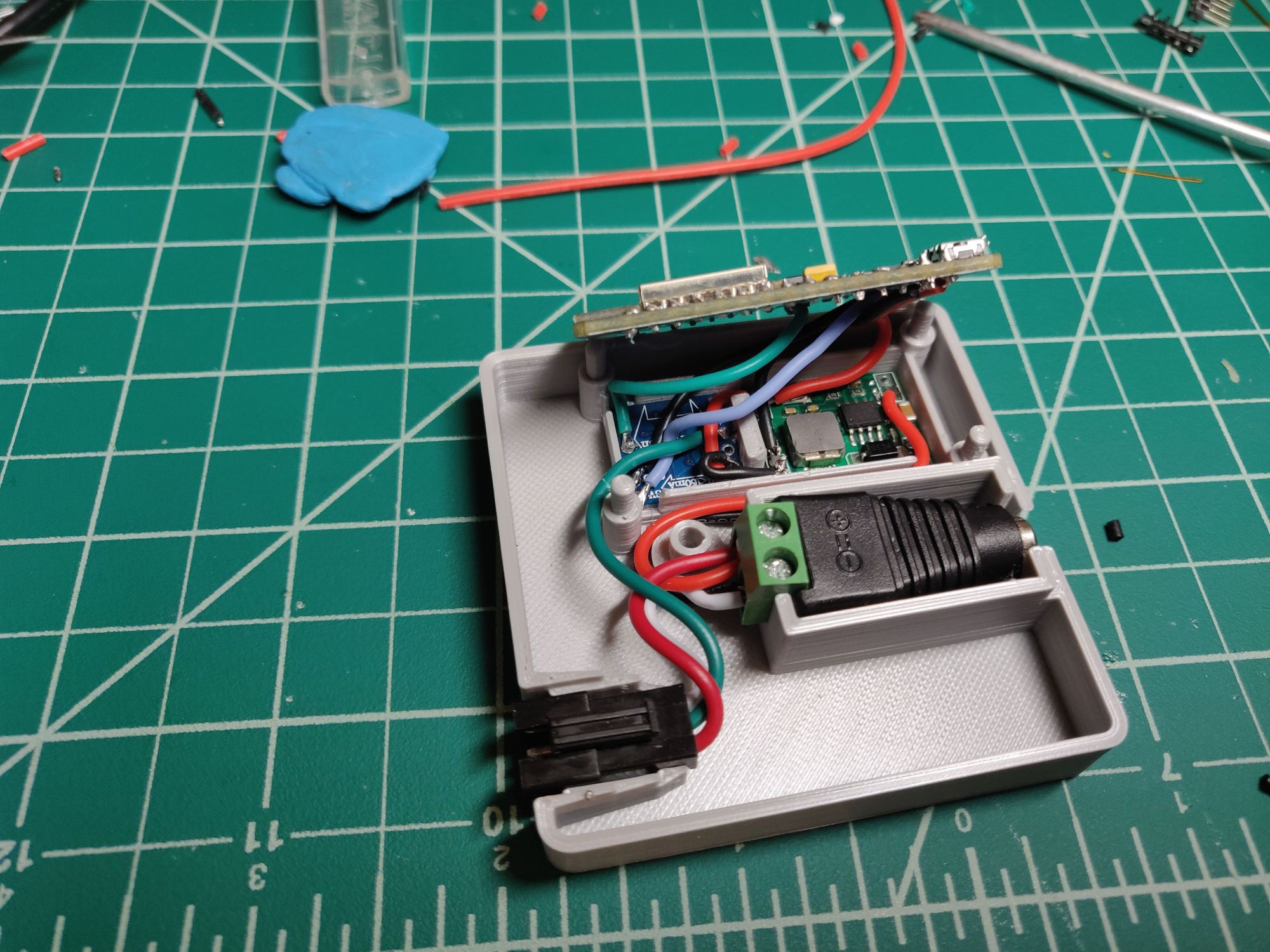
Once you have a steady 5v output move ahead to wiring up the NodeMCU and logic converter as shown in the diagram.
Never connect the NodeMCU to USB power via the MicroUSB and the 12v DC input simultaneously!!! It WILL fry your components.
The logic level converter component is required because the NodeMCU outputs the control signal at 3.3v and the LEDs require this at 5v. The LEDs use this digital signal to drive the WS2811 controllers which then control the LEDs themselves.
Take your time. The pads are small and it takes practice soldering things this small. Double check for continuity using your multimeter before powering things up (this means you haven't accidentally globbed solder and bridged connections). I find tweezers to be very useful. If you have experience building racing drones like I do, you'll find this build tight but easy enough.
Flashing the NodeMCU
Now it's time to flash the NodeMCU with the firmware we're going to use to control the LEDs. To do this we're going to use the Arduino IDE. It runs on Linux (yay!), Mac and Windows. This step is a little hard to explain so I made a short video.
You must make sure the values of the MQTT topics are correct. Also change your wifi details, the OTA updated password, your HASS IP and a couple of other lines. If you'd like multiple LED strips to be controlled at once you could subscribe multiple NodeMCU's to the same topics but you can also use groups in HASS to achieve the same result.
You can find the code I used in on Github.
This repo is a fork of Bruh automation's repo, his code didn't compile for me but this one did.
As I showed in the video after the initial flash you can use the network port flash function (OTA update) to update your NodeMCU remotely in future. No need to plug it in via USB every time! Nifty!!
Home Assistant configuration
My full HASS configuration is available in this Github repo.
The configuration you actually need to drive the LEDs from HASS is surprisingly simple.
light:
  platform: mqtt
  schema: json
  effect: true
  effect_list:
    - bpm
    - confetti
    - cyclon rainbow
    - dots
    - fire
    - glitter
    - juggle
    - lightning
    - noise
    - police all
    - police one
    - rainbow
    - sinelon
    - solid
  brightness: true
  flash: true
  rgb: true
  optimistic: false
  qos: 0
  name: "Chimney LED Strip"
  state_topic: "leds/chimney"
  command_topic: "leds/chimney/set"
Modify this to suit your needs and double check the state_topic and command_topic match the values you entered into the NodeMCU firmware.
Restart HASS and we're good to go!
Ok, Google.
If you look closely in the Github repo containing my HASS configuration you'll see that I have hooked up Google Assistant. Ok, I know the cloud is evil. But this is just a nice option to have and if Google Assistant went away tomorrow everything would continue to function within my LAN without any issues.